August 2007
Monthly Archive
Mon 27 Aug 2007
[ratings]
I know exactly how to make a bandsaw now.
My Designs where to build out the arms: I drew this on deltacad
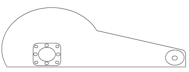
Basically you see that the “boom” of the saw is shaped like the booms you see on regular chop saws. I based this shape off of a Ryobi Chopsaw I had lying around. The whole boom would be made of aluminum plate 1/2 thick. Two would be needed for strength plus to shield the coldsaw blade inside for safety. The mounting plate I designed was for any Browning Gear reducer to be able to mount to it. 35:1 ratio is perfect for a coldsaw (40:1 would do just fine). Once the mounting plate was mounted on the reducer, it would then be secured onto the boom. A two step process to assure that everything will line up squarely. This will attach to the Ryobi chopsaw.
I made sure when I picked out the reducer that it had a 56C face mount. There I would then mate it with a 1-2hp VDC motor. Running the motor is a little tricky because it would require you to have a variac (variac is coined and related to GE electric) device, aka variable transformer, to control the output VAC, then take that VAC and convert it into VDC. I have a diagram I quickly threw together to farther help myself in the planning of this coldsaw:
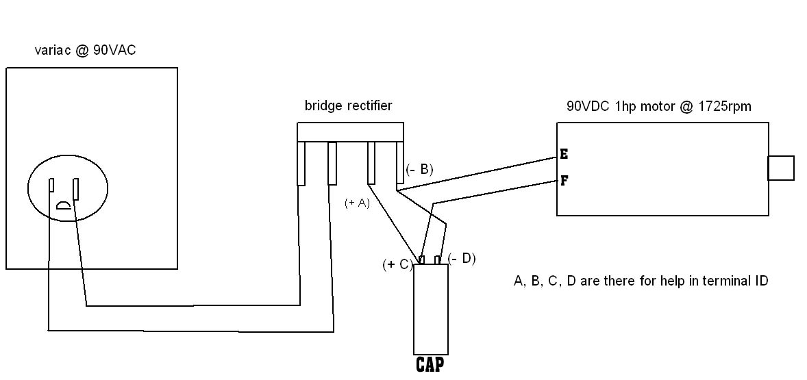
Lets start with a little introduction into AC-DC conversions here. When VDC is converted to VAC and the device that allows this transition, is called an inverter. To do the opposite, we would require a bridge rectifier (BR). The capacitor is there to “smooth” the VDC current to the motor. So I’ll explain whats going on in the diagram:
1) My motor requires 90VDC. I set my variac to dial into 90VAC. The variac’s input is 110/120VAC and the output can vary depending on what you buy.
2) I take the dialed output and run in through the BR. The BR will ouput 90VDC. The 90VDC isn’t clean so the capacitor is needed to “enhance” the current to a more direct current (DC current) to supply the motor.
This is a nice project but in the midst of everything and the chaos, I have temporarily lost interest. I might finish this project; I might not. To ponder a 14″ bandsaw blade mated to the completed device makes me melt inside=)
FYI:
Gearing Ratio calculation:
(Driven Pulley)/(Drive Pulley)= #:1 gearing ratio
RPM calculation:
(motor rpm X Drive pulley)/(Driven Pulley)
F/M calculation:
(RPM)x(circumference of wheelblade in ft)
circumference: pi*D
FPM to RPM calculation: FPM/(PI X wheelblade dia in ft)
Misc. Notes
wheelblade diameter: 12.625″->1.052′
wheelblade circumference: 39.66″->3.305′
120F/M = 36RPM
165F/M = 50RPM
182F/M = 55RPM
198F/M = 60RPM
Material Cut Speed
Mild Steel: 52RPM
Stainless: 26RPM
Aluminum: 90RPM-303RPM Castings require higher speeds because of the silicon content.
Example Calculation of RPM
Motor RPM: 1750 w/1″ pulley
Driver Pulley: 4″ w/1″ pulley
Driven Pulley: 4″ pulley
1) This gives a 4:1 ratio. So 4/1= 4. 1750/4 = 437.5RPM
2) Driver pulley is connected to the Driven pulley @ 437.5RPM via 1″ pulley. This again, gives us 4:1 ratio. 437.5/4 = 109RPM.
Together, we have 16:1 ratio or 1750/16 = 109RPM
homemade coldsaw : build a coldsaw
Sat 11 Aug 2007
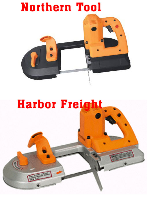
Why do I get the feeling these two models are the same? Other than the color differences? Both are made from the same company but NT chooses to sell it under their label. [HF item# 47840-1VGA] & [NT item# 56245 ]. Took both of their photos and did a comparison. You decide!
Fri 10 Aug 2007
I ordered a 20cf argon bottle and got instead, an 80cf. Awesome! Loving it! I love when the screw up only if it’s to my benefit=)
Wed 8 Aug 2007
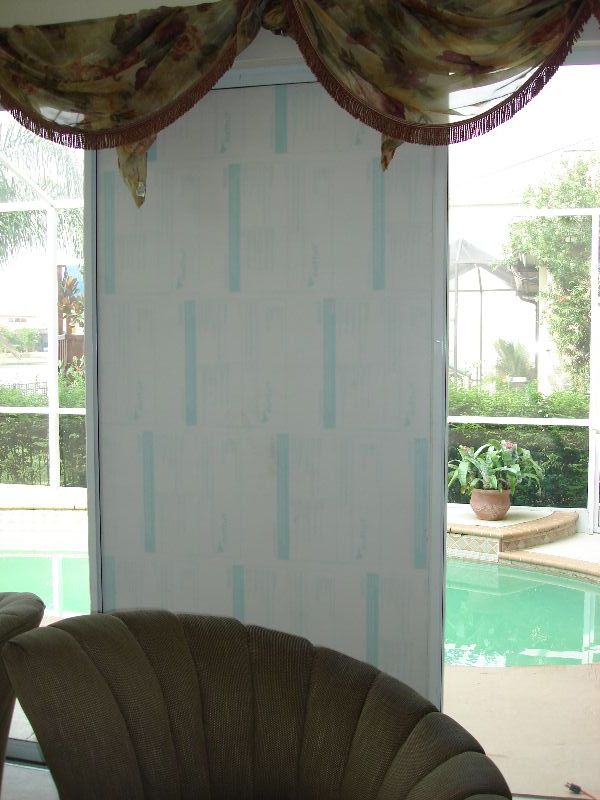
So I was trying to be handy and it got the best of me! I was trying to install a lock for the sliding window and “crack”, the window shattered into millions of pieces.
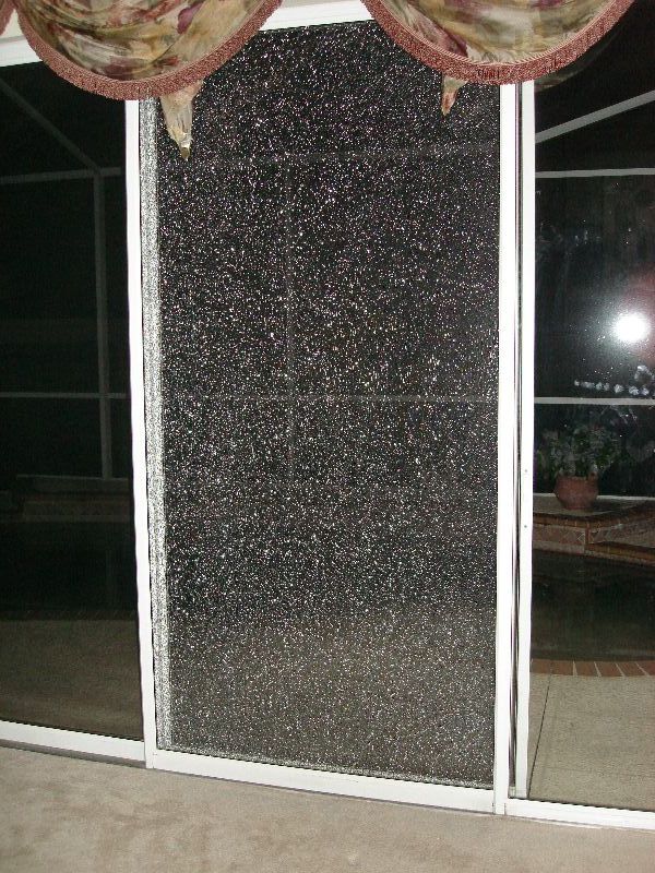
So I quickly ordered another piece but instead of being glass, it is polycarbon plastic. Cheaper and practically unbreakable. The install was a breeze. Had some help holding it while I put piece it together. A little bit of soapy water goes a long ways. No more handy man for awhile. This one set me back a bit.
Mon 6 Aug 2007
[ratings]
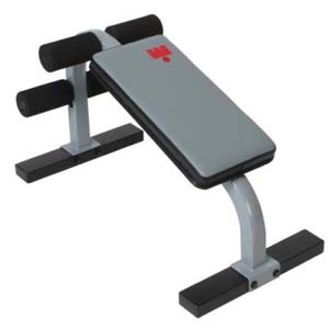
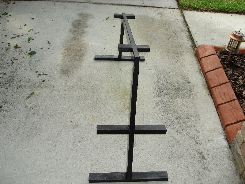
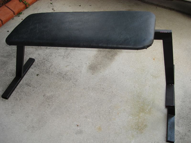
I wanted an ab machine. They are not pricey and I thought to myself that it would be awesome if I made my own. Thinking it would cost me twice as much…. Nope. Cost me 11dollars in materials. Beat that! I originally wanted this:
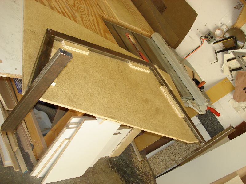
I purchased 12ft of 12×1 steel square tubing. I knew what I wanted in my head. I had it cut down to 6ft lengths then welded them together once I got to the shop. That way it would save me time at the end. I sanded all the rust off with the DA sander. Hence why the steel was so inexpensive.
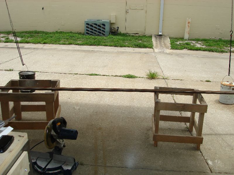
Cut them down to size as desired by my plans.
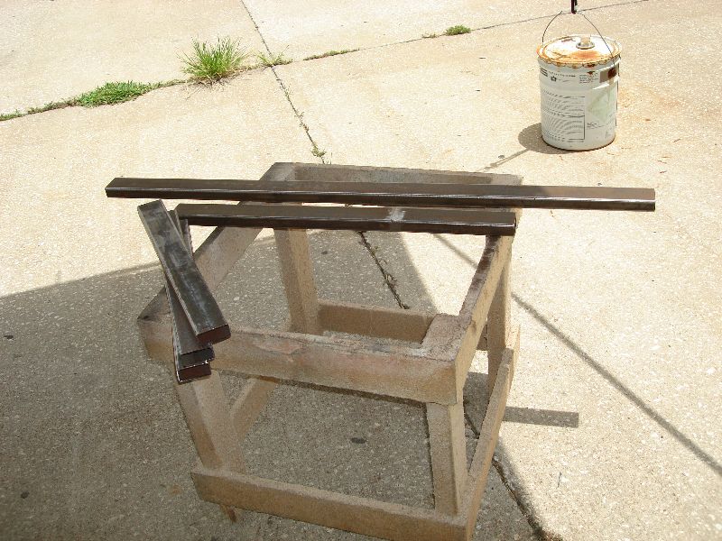
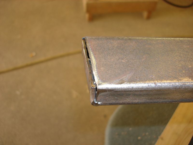
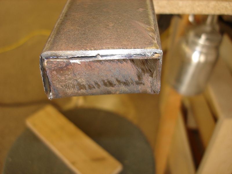
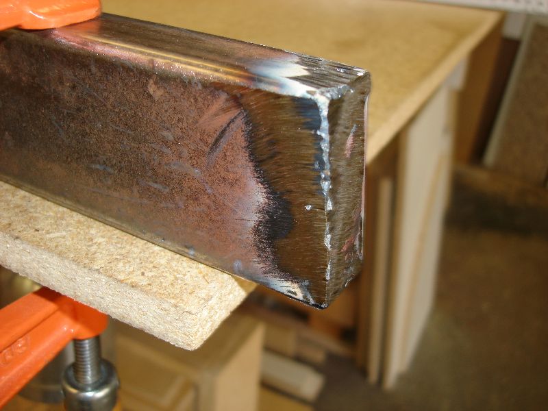
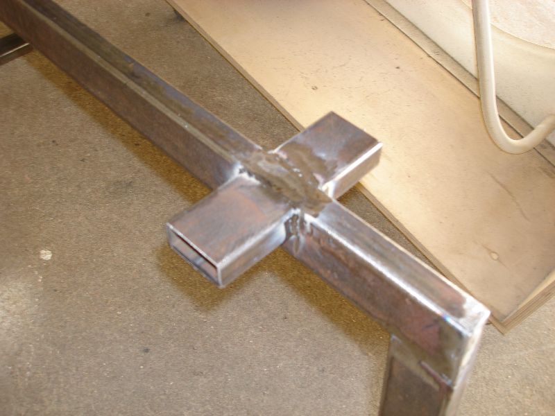
The ends were folded together and welded to create a closed tube plus to minimize injury during use.
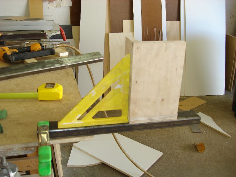
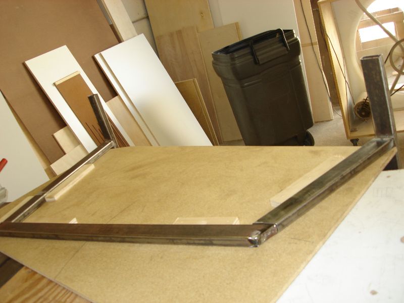
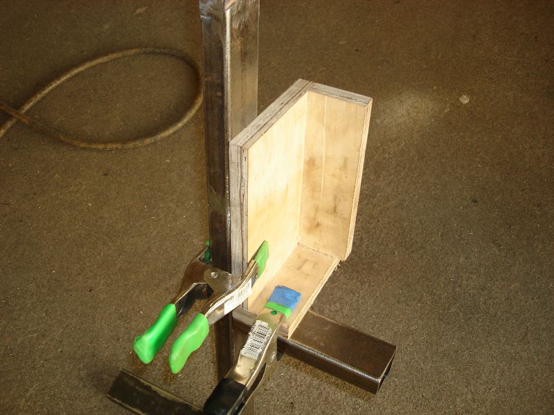
I made a jig to setup the pieces and for easier assembly because of the differing angles. Made sure things were square and plumb
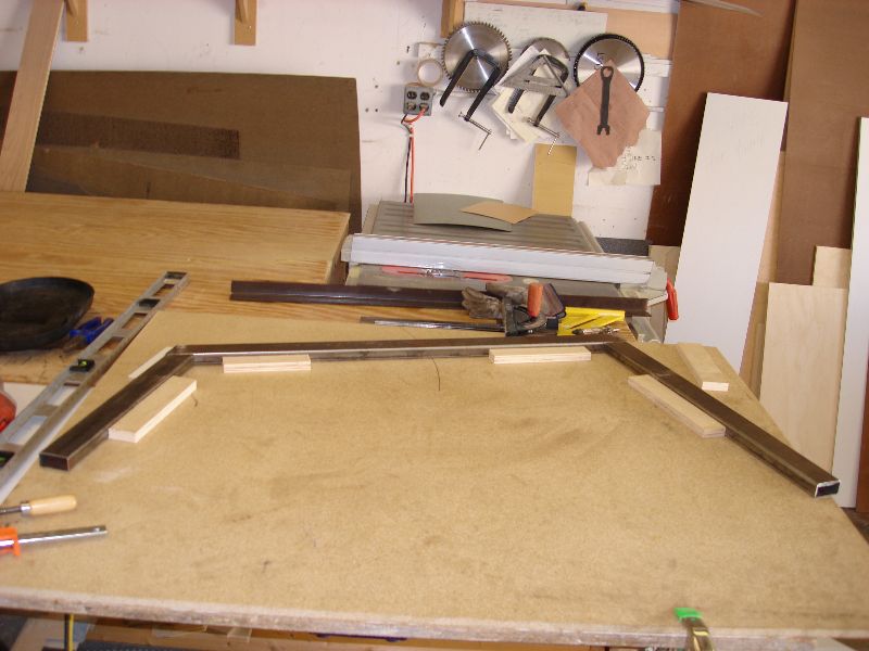
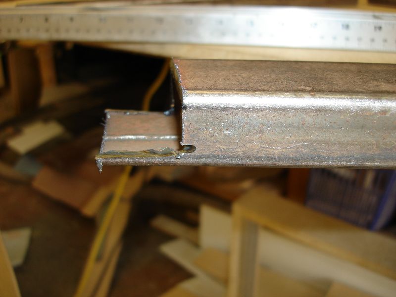
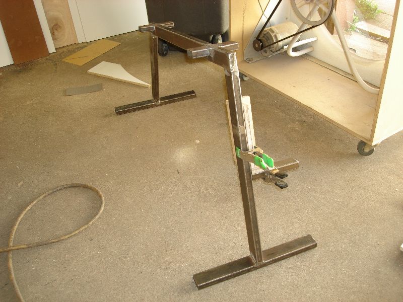
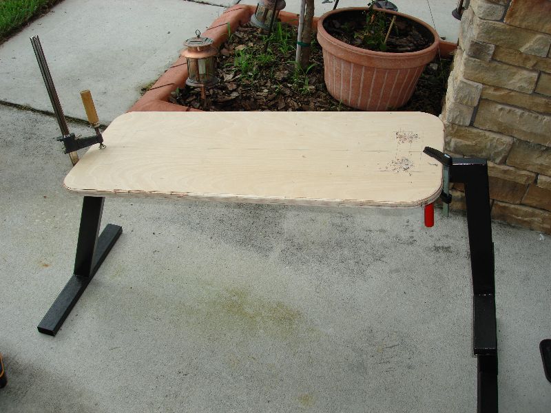
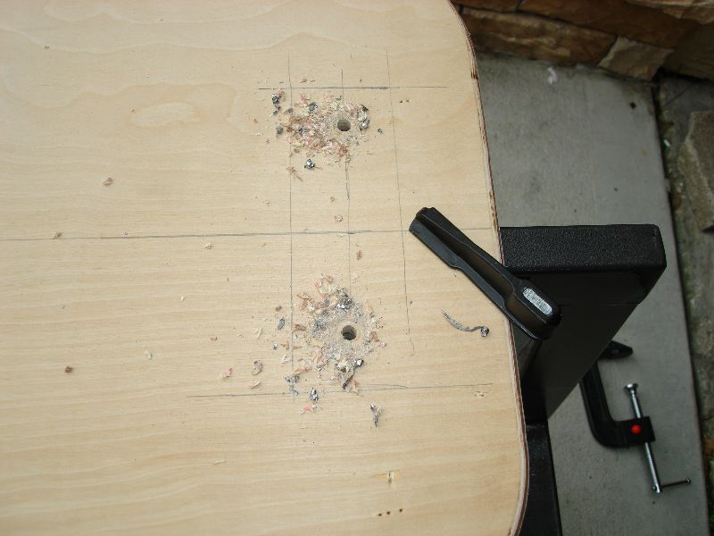
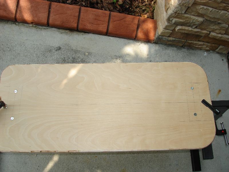
Once I got the legs welded, I laid them on the jig to make sure they fit nicely and then proceeded in welding it all together. I cut 2.5″ pieces and welded them on the side to give placement for backboard attachment.
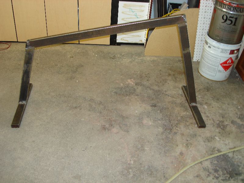
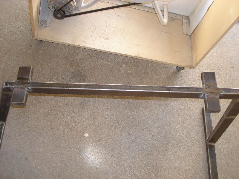
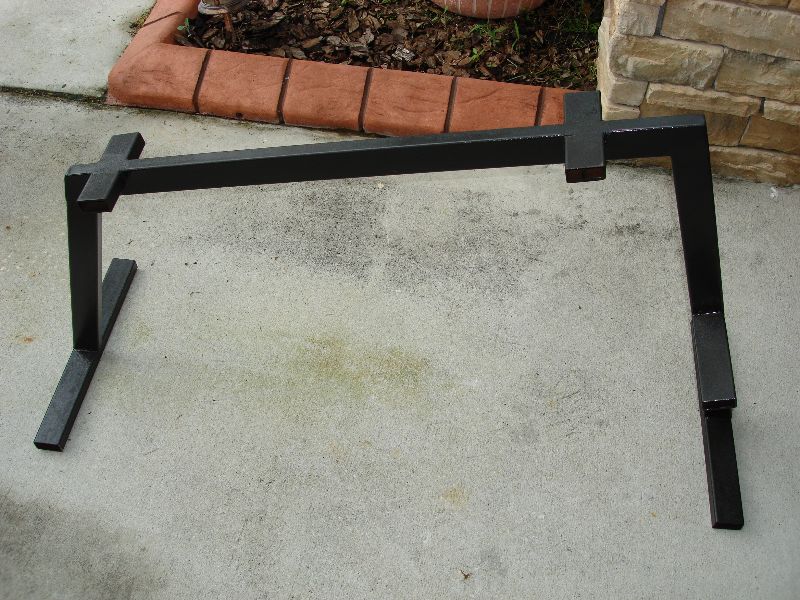
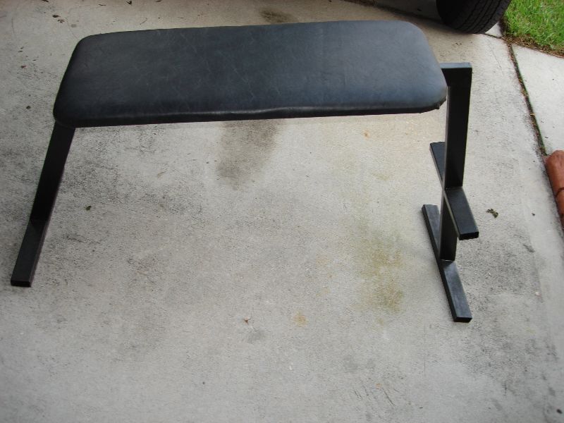
Lastly, I added the feet hold/grasp thingy so that you can hold on it with your feet and use it to pull yourself up when working on your abs.
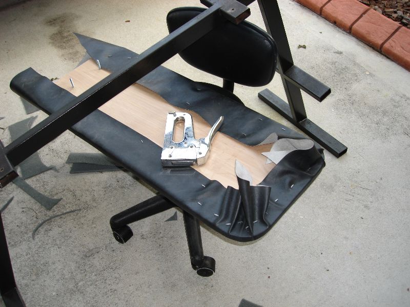
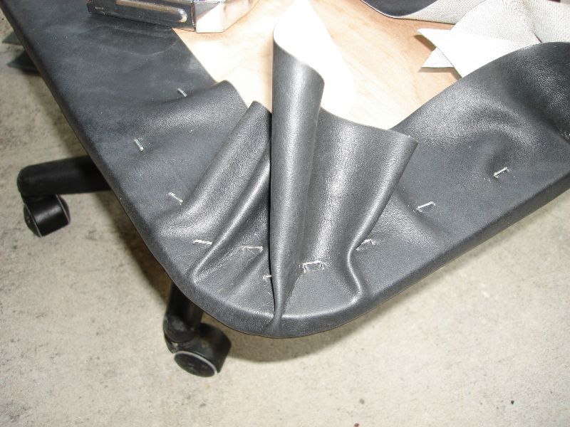
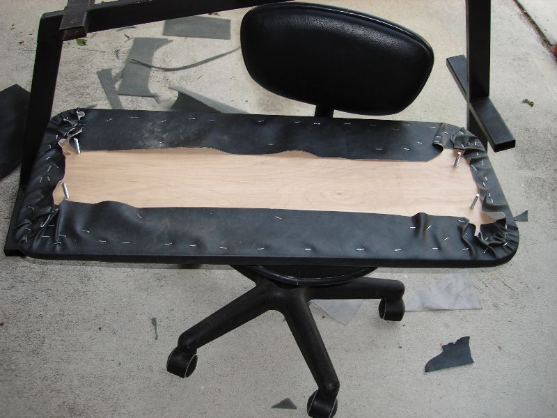
I painted the frame with black Rust-Oleum gun metal textured paint. I looks really good In my opinion. I added the back support and soon will add the cushions for it so I can start on my six-pack.
Ab Machine : Building Ab Machine
Mon 6 Aug 2007
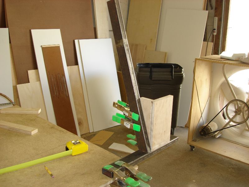
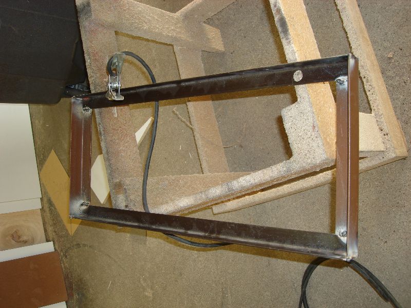
I wanted to make a welder cart for my welder. I know, I could buy one but what’s the fun in that right? So I drew out some preliminary plans based on some of the popular carts I saw around the web. They include:
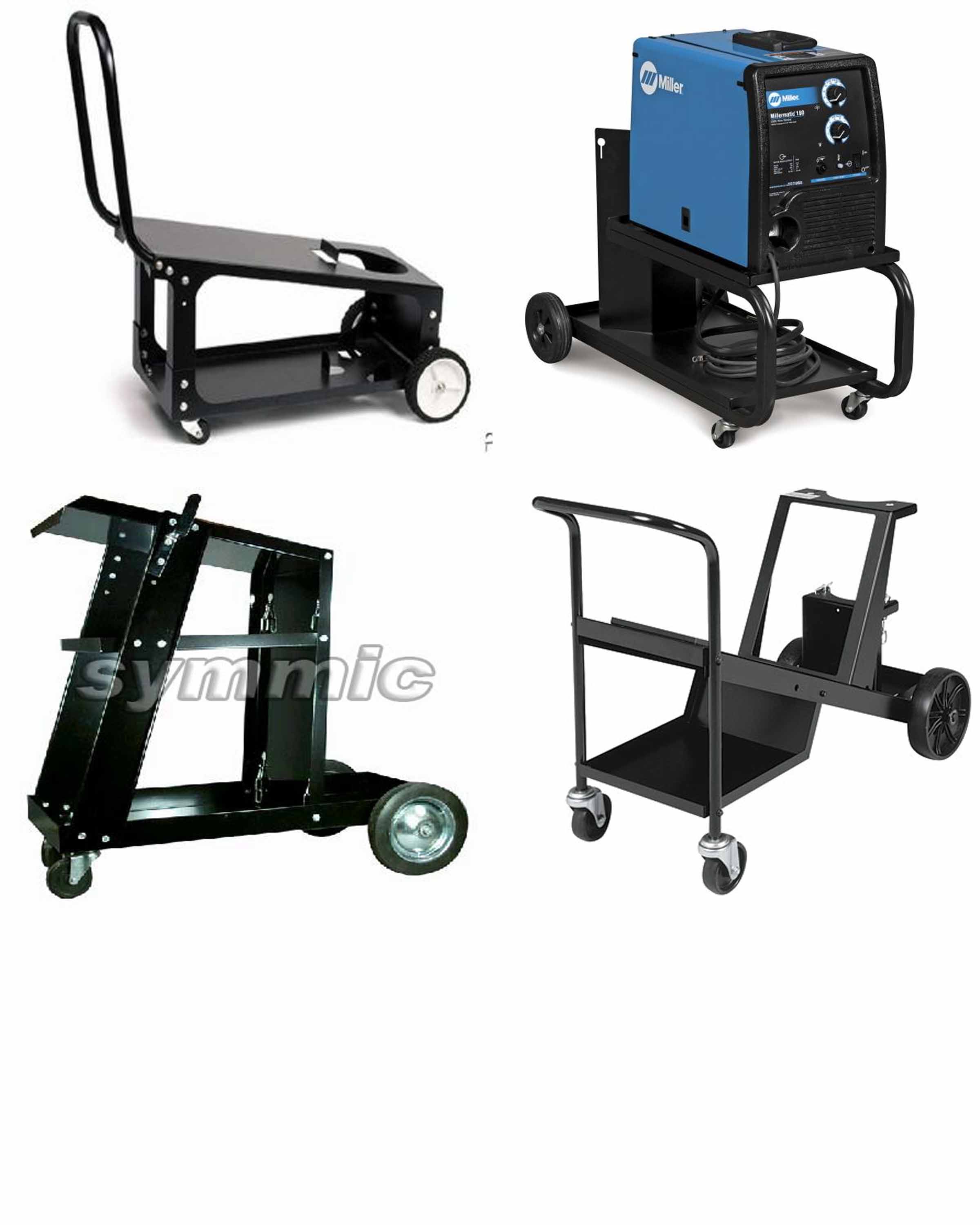
So I chose the top right corner cart. Made something similar to it. It was fun because all the raw material I had was used bed frames. I knew I would need it one day and so I saved them. I still have a lot more left for other projects. I saved them because they are “L” shaped and holds a true line.
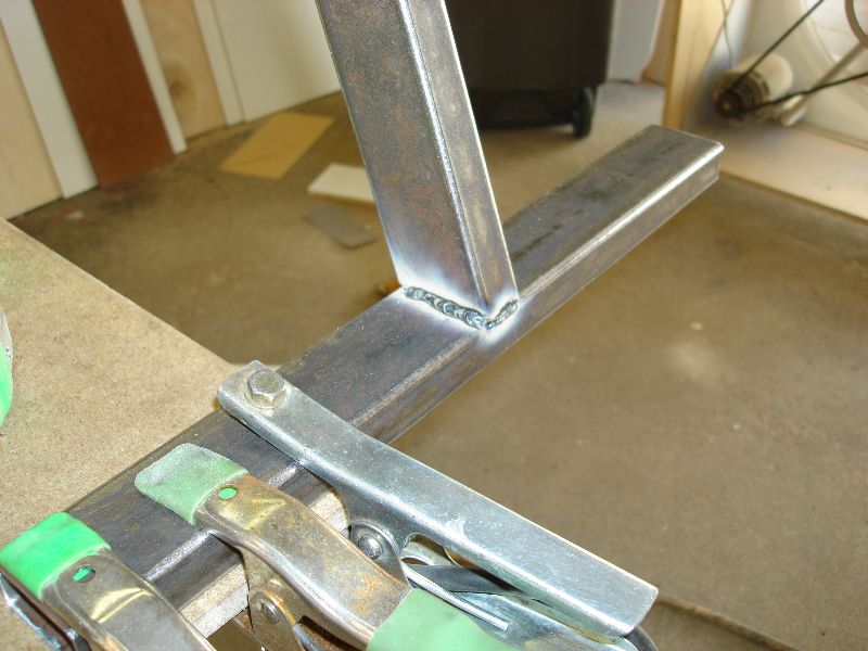
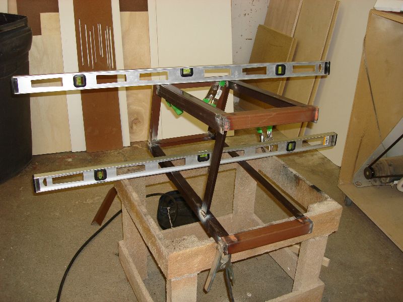
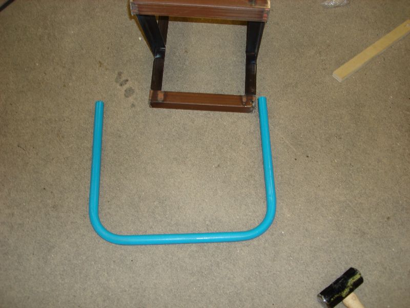
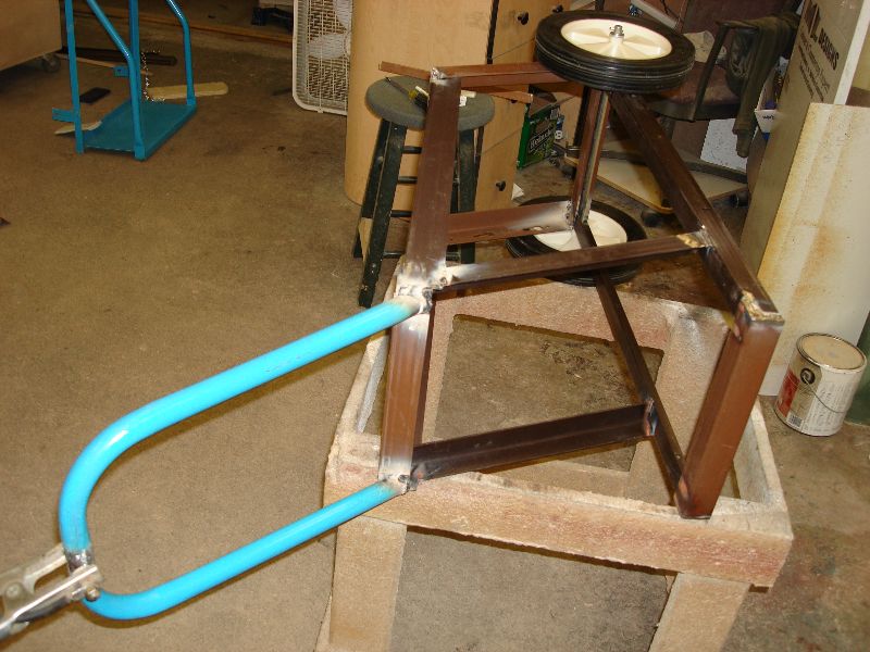
The cart measures 30x12x12. I had it arched up in the front so really it’s 12×15 @ a 15degree angle. You’ll see what I mean when you look at the photos. I took great care in making sure that the bottom was square. I used lots of clamps and was accompanied by a swear-jar.
The platform I used to lay the cart on was not leveled because of the floor having a slight downward grade. So I used two levels to make sure the top and bottom of the cart matched.
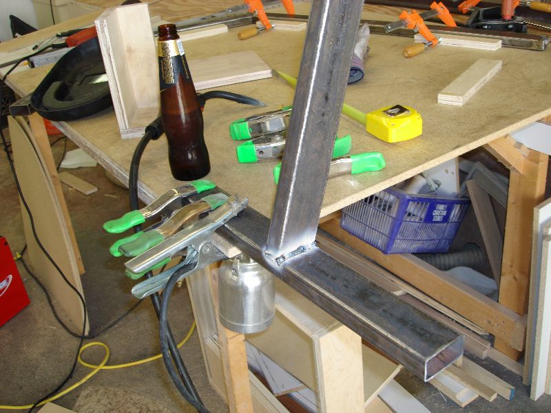
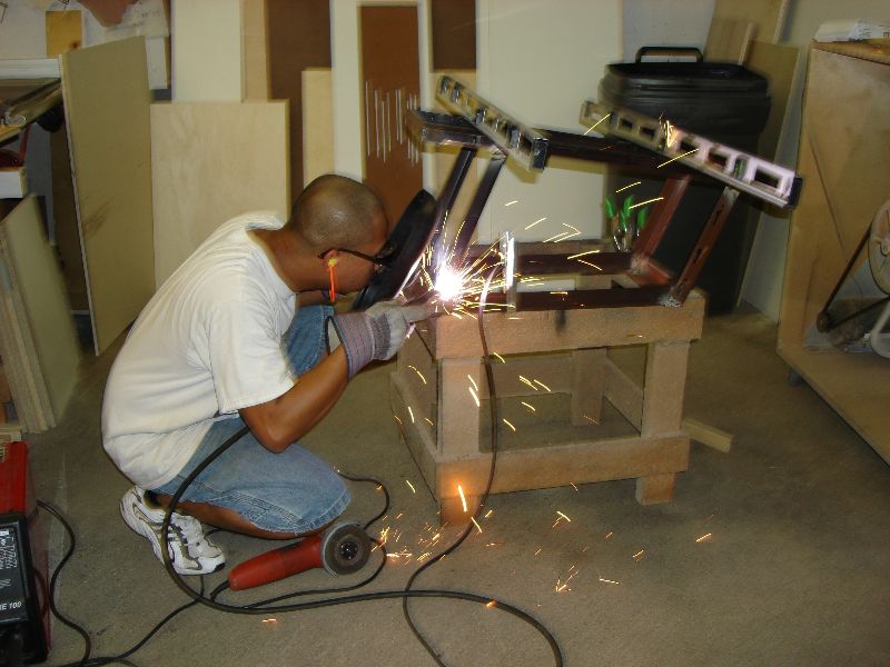
Misc shot of me welding it together and finishing up
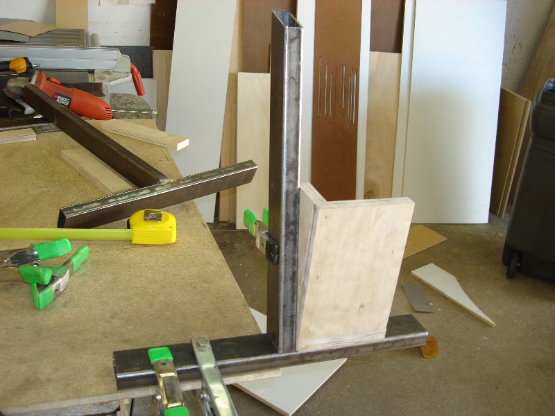
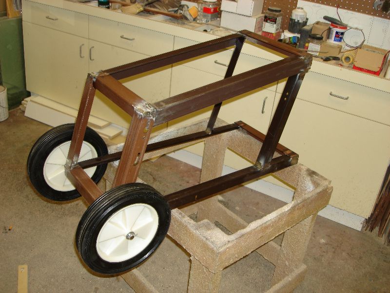
I reused the wheels off of another cart my friend purchased for me (he got the wrong one).
This is how my welder will fit on there when completed.
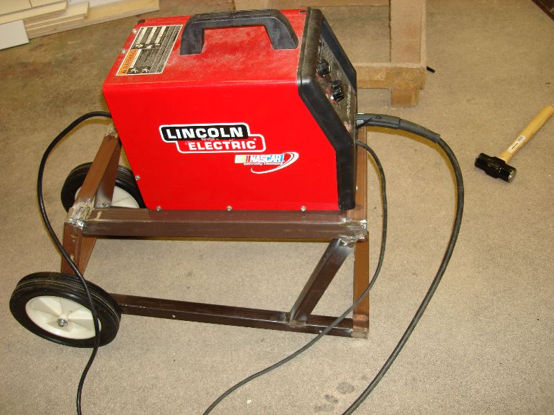
Again, I reused the handle that came off the old one. I Cut it in half, the ends are cut at 45degree angles, then welded to the cart.
I’ll paint it black and be done with it!
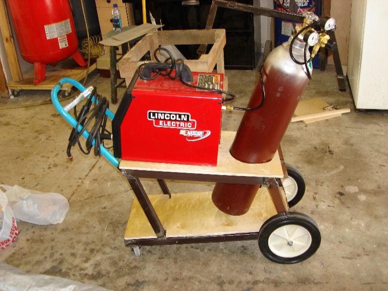
:::UPDATE::::
I’m finally done with my welding cart. Took me three weeks to do it because I can only work on it on the weekends. Turned out great! For some reason, I like making my own tools lately. Sometimes I save a lot of money and sometimes It costs more to make something than buying it new. That’s besides the point because making it is far better then buying one at any rate.
I originally designed my cart for a 20CF argon/co2 tank but I ended up having a 80CF tank instead so the dimensions needed some reworking. I love my welder now; welds are so pretty and clean. Fits nicely on the cart. I never new how heavy everything was. Toting it around the shop on the cart is so much easier on my back then when I had to carry everything. I’m not doing that again! Mobile welder on a cart is something you don’t want to do without.
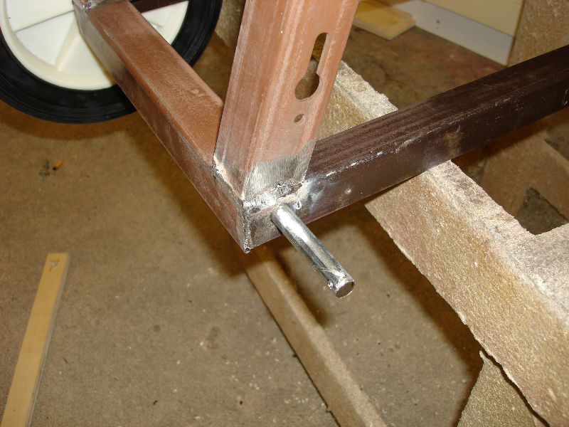
I welded the front caster wheels on Sunday morning. They were galvanized coated and so I had to grind it off prior to welding it on. The angle is just right. I put a box in front of it to put my misc odds in there. It’s not pictured of course but you get the idea. I chose plywood as a platform because it’s much easier to cut than if it were out of mild or aluminum stock.
I was going to paint it but I ended up leaving it the way it is. Works just fine and serves one main service: to tote my welder + argon tank around the shop. It’s made out of used bed frames. I like how the mismatched colors came together; brings out the true luster=)
Build Welder Cart : Homemade Cart : Homemade Welder Cart : Making A Welder Cart
Fri 3 Aug 2007
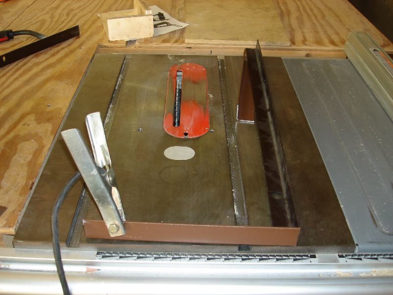
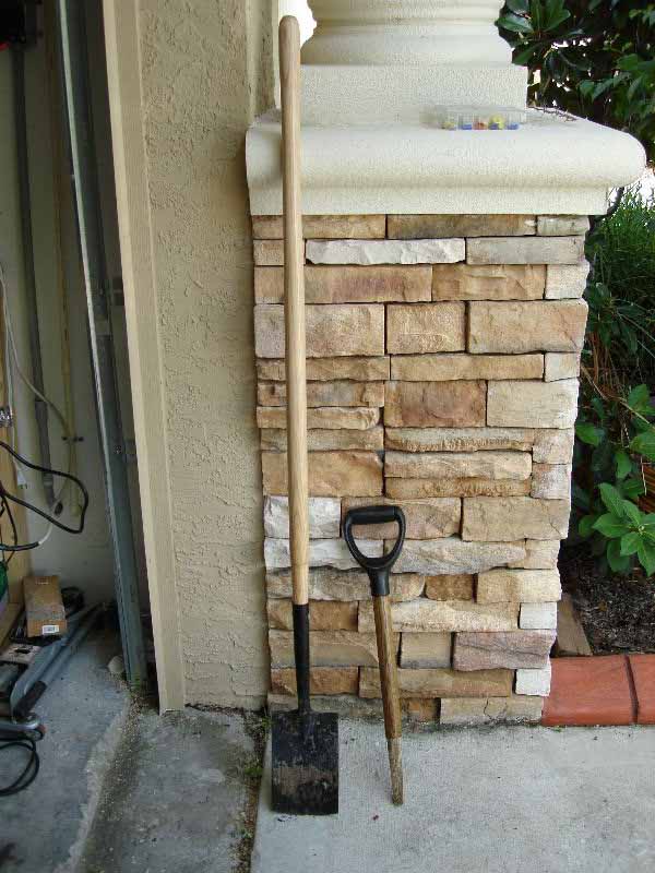
I purchased the new handle a month ago from Home Depot I believe and just now installed it. It was pretty easy. I ground the aluminum pin that was holding the blade to the handle and knocked it out with a nail:
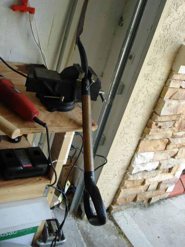
Also as you can see the new vise I have and are using; it’s my new vice. I purchased a 3lb hammer you’ll see in the third photo.
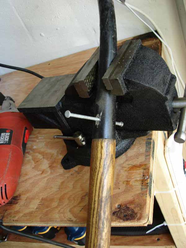
As you can see, I have more leverage. Love the new handle.
Thu 2 Aug 2007
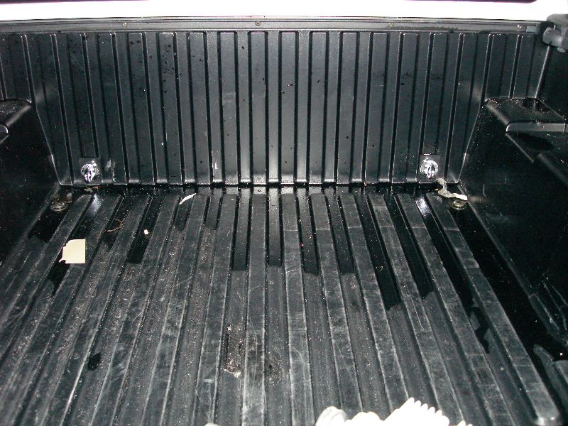
Ever needed to strap something down say 10ft long conduits or PVC piping and you have a short bed? You can strap it down near the end by the tail gate but thats all you can do. Now you have one end flopping up and down whilst you drive and it could fall out and cause an accident!
When I transport pipes of those sizes, I usually have the tailgate up and the pipes slid in on an angle resting on the tailgate. The rear is secured but if you don’t secure the other end that is slid in, you have the possibility of having the pipes fall out when you go over just a small grade or hump on the road.
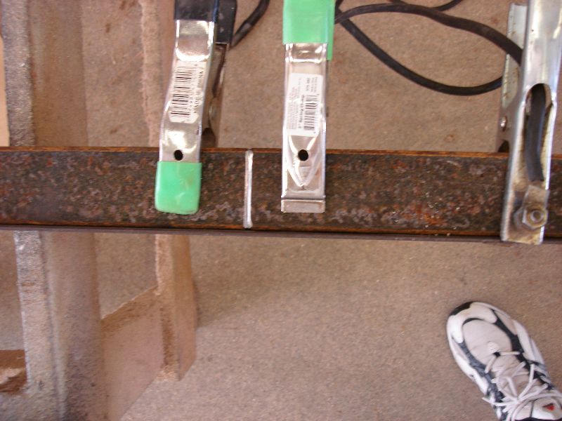
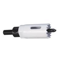
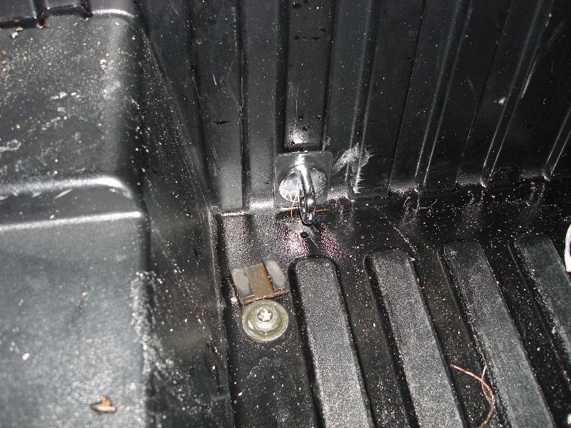
I tried to tie it down both ends but the my anchor points are high near the edge of the bed. I needed something low near the bed so I purchased some anchors 2 years ago and just now installed them tonight. They work real well because they come with toggle bolts that help secure the anchors to the bed of the truck. Though I had to drill two holes of 1.125″ wide through fiberglass which was a pain- should of worn gloves! I used a Lenox bit. It took less than 5 seconds to drill through the .25″ thick fiberglass bed liner.
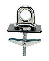
Here are some shots of the finished product. I used liquid nail adhesive to farther secure them onto the fiberglass surface. I torqued them by hand till I couldn’t turn them anymore. They fit snuggly.
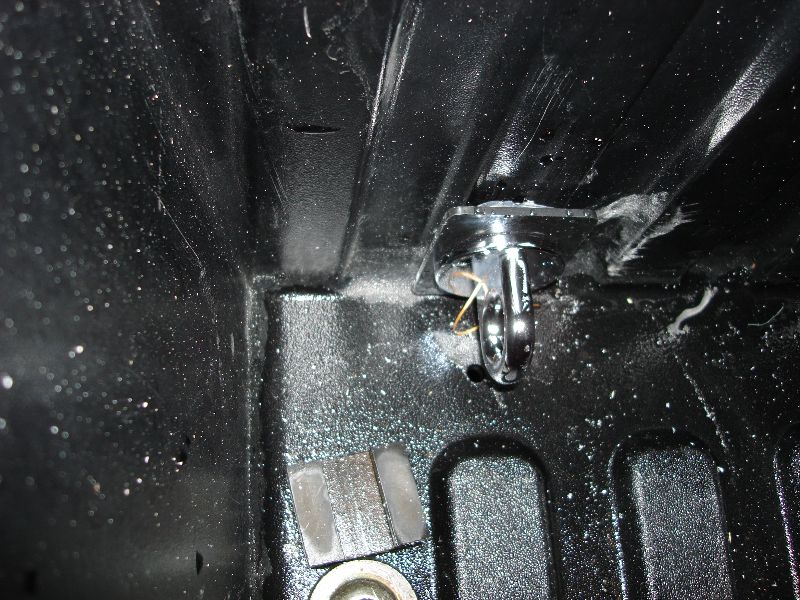
This is the first I’ve every seen on my truck. I claim dibs.