Mon 27 Aug 2007
[ratings]
I know exactly how to make a bandsaw now.
My Designs where to build out the arms: I drew this on deltacad
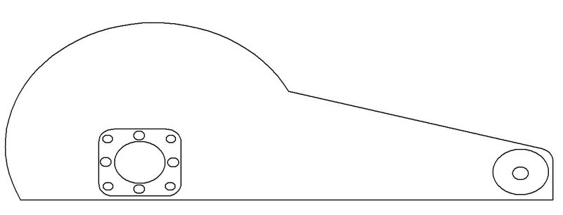
Basically you see that the “boom” of the saw is shaped like the booms you see on regular chop saws. I based this shape off of a Ryobi Chopsaw I had lying around. The whole boom would be made of aluminum plate 1/2 thick. Two would be needed for strength plus to shield the coldsaw blade inside for safety. The mounting plate I designed was for any Browning Gear reducer to be able to mount to it. 35:1 ratio is perfect for a coldsaw (40:1 would do just fine). Once the mounting plate was mounted on the reducer, it would then be secured onto the boom. A two step process to assure that everything will line up squarely. This will attach to the Ryobi chopsaw.
I made sure when I picked out the reducer that it had a 56C face mount. There I would then mate it with a 1-2hp VDC motor. Running the motor is a little tricky because it would require you to have a variac (variac is coined and related to GE electric) device, aka variable transformer, to control the output VAC, then take that VAC and convert it into VDC. I have a diagram I quickly threw together to farther help myself in the planning of this coldsaw:
![]()
Lets start with a little introduction into AC-DC conversions here. When VDC is converted to VAC and the device that allows this transition, is called an inverter. To do the opposite, we would require a bridge rectifier (BR). The capacitor is there to “smooth” the VDC current to the motor. So I’ll explain whats going on in the diagram:
1) My motor requires 90VDC. I set my variac to dial into 90VAC. The variac’s input is 110/120VAC and the output can vary depending on what you buy.
2) I take the dialed output and run in through the BR. The BR will ouput 90VDC. The 90VDC isn’t clean so the capacitor is needed to “enhance” the current to a more direct current (DC current) to supply the motor.
This is a nice project but in the midst of everything and the chaos, I have temporarily lost interest. I might finish this project; I might not. To ponder a 14″ bandsaw blade mated to the completed device makes me melt inside=)
FYI:
Gearing Ratio calculation:
(Driven Pulley)/(Drive Pulley)= #:1 gearing ratio
RPM calculation:
(motor rpm X Drive pulley)/(Driven Pulley)
F/M calculation:
(RPM)x(circumference of wheelblade in ft)
circumference: pi*D
FPM to RPM calculation: FPM/(PI X wheelblade dia in ft)
Misc. Notes
wheelblade diameter: 12.625″->1.052′
wheelblade circumference: 39.66″->3.305′
120F/M = 36RPM
165F/M = 50RPM
182F/M = 55RPM
198F/M = 60RPM
Material Cut Speed
Mild Steel: 52RPM
Stainless: 26RPM
Aluminum: 90RPM-303RPM Castings require higher speeds because of the silicon content.
Example Calculation of RPM
Motor RPM: 1750 w/1″ pulley
Driver Pulley: 4″ w/1″ pulley
Driven Pulley: 4″ pulley
1) This gives a 4:1 ratio. So 4/1= 4. 1750/4 = 437.5RPM
2) Driver pulley is connected to the Driven pulley @ 437.5RPM via 1″ pulley. This again, gives us 4:1 ratio. 437.5/4 = 109RPM.
Together, we have 16:1 ratio or 1750/16 = 109RPM
homemade coldsaw : build a coldsaw
One response to “Homemade Coldsaw”
Leave a Reply
You must be logged in to post a comment.
I’m assuming someone couldn’t sleep.